The hydraulically driven fuel injection pump transmits the hydraulic pressure of the accumulator directly into very high fuel pressure (3.500 bar / 50,800 psi). The injection through a large number of very small slots at the circumference of the combustion chamber (Picture below), results in a homogeneous distribution of highly atomized fuel in the combustion chamber and nearly prevents the impingement of fuel at the cylinder wall, as shown in the graph Peripheral Fuel Injection, below. This arrangement provides significantly improved preconditions for a Homogeneous Charge Compression Ignition (HCCI) operation, including the emissions of soot and NOx. The HC and CO emissions are generally relatively low in Diesel engines, and the CO2 emissions are reduced proportionally to the fuel consumption.
The improvements in the Quality of Combustion are based on a comparison with current systems where fuel injectors have a small tip with 6 to 8 closely spaced micro holes for injecting the fuel, resulting in a high concentration of fuel beams with insufficient access to oxygen, creating a delayed, incomplete combustion with lower efficiency and higher emissions.
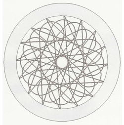 Peripheral Fuel Injection (PFI)
It is expected, that the high efficiency of large ship Diesel engines (155 g/kW*h - due to low cylinder wall heat losses and no impingement of fuel) are compensated through the higher combustion efficiency, quality of fuel, thermal barrier coating (TBC) and reduced mechanical friction of the HFPE. The higher rpm. of auto-motive 4-stroke engines is compensated through the doubling of power strokes of the less heat sensitive 2-stroke HFPE, noticeably higher brake mean effective pressure (BMEP 35 bar) and reduced losses of combustion heat and friction.
Achieving the high expected thermal efficiency of 63% is based on improved dynamic behavior of the free-piston principle (lower heat losses due to faster piston acceleration, closer to constant volume combustion), smaller combustion chamber surface area (-35%) with ceramic coating (TBC) to reduce heat losses, and efficient recuperation of exhaust energy through the Piston Impulse Charger & Compounder (PICC). Considering the low friction losses of the HFPE and additional hydraulic losses (7%) for controlling the pistons and driving the fuel injection pump, a reduction of 30% in Brake Specific Fuel Consumption (BSFC) to 140 gr/kW•h (0.230 lb./hp.h) is expected.
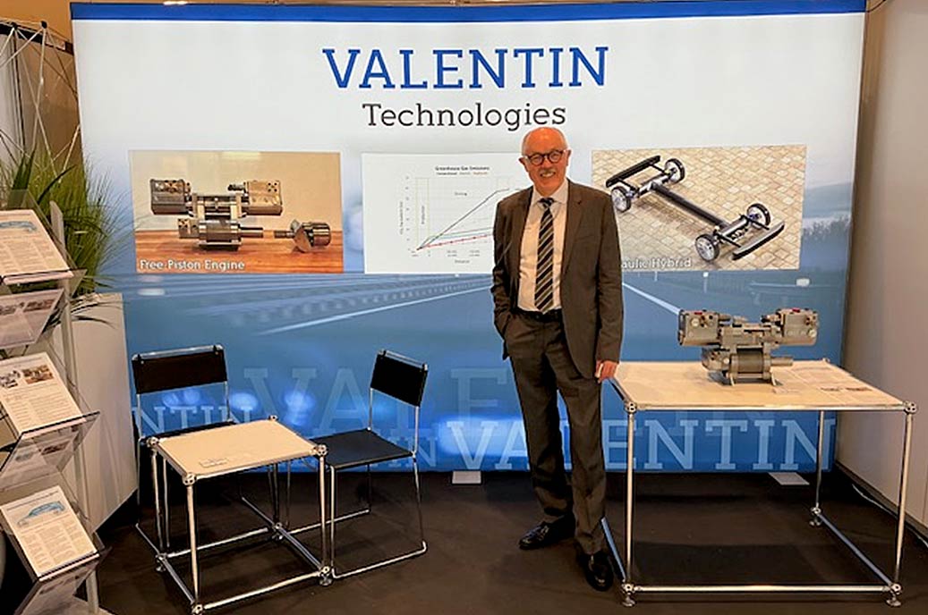
Display at the 12. International Engine Congress, Febr. 25. – 26. 2025, Baden-Baden, Germany.
 Hydraulic Axial-Piston Motor
Hydraulic motors for road vehicles must be very efficient, small, light, and their displacement adjustable to adapt to the driving conditions regarding speed and torque. The required high operating pressures can reliably obtained only with piston units. Axial-piston motor types provide, in comparison with radial-piston units, a wider range of adjustment, and higher rotational speed, and power density. Of those, bent-axis type axial-piston motors have currently a wider range of adjustment and speed and less mechanical losses, but are noticeably larger and heavier, more expensive, and have a shorter theoretical lifetime expectancy. The motor for the Ingocar is a 'Swashplate-Type' unit with a tilt angle of 32 degrees.
Operating ranges, new and current hydraulic motors
The new motor is an axial-piston, swashplate-type unit. Several patented and new features result in a reduction in size and weight (-60%), an increase in maximum speed (+75%) and a larger Tilt angle (+57%). The wider range of the displacement adjustment (tilt angle), and significant decrease in fluid, friction and compression losses - especially in areas of low powers - increases the operating range by a factor of more than 5.
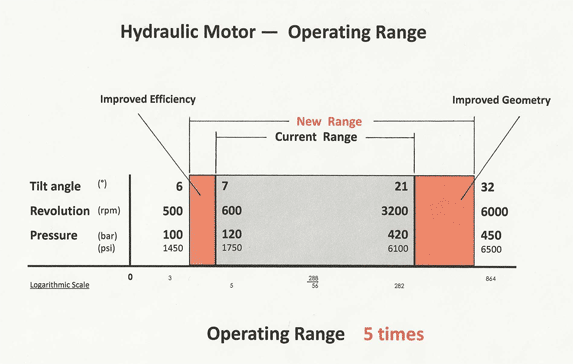 The concept is scalable over a wide area, from 10 to 10.000 kW (14 to 14,000 hp). The specific weight (kW/kg / hp/lbs.) is increased by a factor of 6. The Diagram shows the operating ranges of the best current motors in comparison to those of the new motor.
Compared with electric motors for automotive drivetrains, the new hydraulic motor has a 5 times higher specific power density (kW/kg / hp/lbs.) and a high reduction in specific volume (kW/Liter / (hp/cu.in.) In addition, control and cooling are noticeably simpler.
Based on the new motor geometry, the critical mechanical loads are lower and the mechanical friction losses reduced through Diamond-Like-Coating (DLC) by more than 50%.
The smaller size and shorter sealing areas reduce the external leakage by more than 30%. A significant reduction of internal leakage, generally the largest portion of losses, is reached through new design features.
U.S. Patents, International Patents pending.
Copyright Valentin Technologies